The integrity of any high-density polyethylene piping system relies entirely on the precise dimensional matching of pipes and fittings. Confusing Nominal Diameter (DN), Outside Diameter (OD), Standard Dimension Ratio (SDR), and Nominal Pressure (PN) leads to faulty fusion joints, pressure failures, and costly procurement delays. When field crews attempt to fuse mismatched components, the resulting weak joints fail under pressure testing or during active service. Engineers must understand these parameters to ensure system reliability. This guide serves as a definitive technical resource for navigating ISO 4427 and ASTM sizing standards. We provide the necessary data to specify, evaluate, and procure the correct fittings for industrial, municipal, and commercial applications. Using an accurate HDPE pipe fittings size chart eliminates guesswork, ensuring your pipeline infrastructure handles the required flow and pressure without structural compromise.
OD is Constant, ID Varies: The outside diameter (OD) of HDPE pipe and fittings remains constant for a given nominal size, while the inside diameter (ID) fluctuates based on the wall thickness dictated by the SDR.
SDR Dictates Pressure Capacity: A lower Standard Dimension Ratio (SDR) indicates a thicker wall and higher pressure rating (PN or PSI). SDR 11 will withstand higher pressure than SDR 17.
Multiple Sizing Standards Exist: Engineers must explicitly identify whether a system utilizes Metric (mm), Iron Pipe Size (IPS), or Copper Tube Size (CTS) standards before consulting an HDPE pipe fittings size chart.
Fusion Compatibility is Non-Negotiable: For reliable butt fusion welding, the SDR and wall thickness of the fitting must exactly match the SDR and wall thickness of the adjoining pipe.
Material Grade Matters: Sizing charts must be evaluated in the context of the resin grade (e.g., PE100 vs. PE80), as PE100 achieves higher pressure ratings at the same wall thickness compared to legacy materials.
Table of Contents
Toggle
HDPE Pipe Fittings Size Chart: Metric, IPS, CTS, and SDR
Contractors and engineers frequently mix up metric and imperial sizing conventions on international job sites. Misinterpreting a single acronym on a material submittal causes severe specification errors. You must decode these terms accurately to select the correct components for your pipeline. A minor misunderstanding of a dimension ratio results in ordering materials that simply cannot be fused together in the trench.
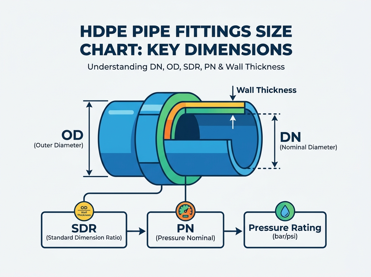
Nominal Diameter (DN) vs. Outside Diameter (OD)
DN represents the European metric standard designation for size. It acts as a convenient label during the initial design phase rather than an exact physical measurement. For example, a DN 100 pipe does not measure exactly 100 millimeters in any dimension. Engineers use DN to categorize pipe classes on drawings, but it lacks the precision required for machine calibration.
OD stands for the exact, measurable outside diameter. This dimension dictates how the pipe interacts with fusion equipment. The heating plates, facing tools, and clamping jaws of a butt fusion machine rely on the exact OD to secure the pipe and apply uniform interfacial pressure. If you set up a machine for a 110mm OD pipe, it will not properly grip a pipe that deviates from this measurement.
HDPE systems maintain a constant OD regardless of the pressure rating. This constant OD ensures that fusion tools and mechanical fittings clamp perfectly onto the pipe exterior. If the OD fluctuated with every pressure class, contractors would need different fusion machines and inserts for every single wall thickness on the market. The inside diameter absorbs all the dimensional changes as the wall gets thicker or thinner.
Standard Dimension Ratio (SDR) vs. Dimension Ratio (DR)
The structural geometry of the pipe relies on a simple formula: SDR = OD / Minimum Wall Thickness. You use this ratio to understand how much polymer separates the internal fluid from the outside environment. A 110mm pipe with a 10mm wall thickness has an SDR of 11.
All SDRs are DRs, but SDR refers specifically to an internationally standardized series of preferred numbers based on the ANSI preferred number series. Common SDR values include 9, 11, 13.6, 17, 21, and 26. These specific numbers align with standardized pressure classes across the industry. DR can represent any calculated ratio outside these preferred series, which you might see in custom manufacturing or specialized conduit applications.
An inverse relationship exists between the ratio and wall thickness. A lower SDR means a thicker pipe wall. Thicker walls handle higher internal pressures and greater external loads. An SDR 9 pipe features a much thicker wall than an SDR 17 pipe of the exact same outside diameter, making it heavier and more pressure-resistant.
Nominal Pressure (PN), PSI, and Wall Thickness (en)
PN indicates the maximum allowable operating pressure in bar at a baseline temperature of 20°C. A PN10 rating means the system safely handles 10 bar of pressure continuously over a 50-year design life. European, Asian, and Australian projects rely heavily on the PN classification system for water and gas networks.
North American ASTM standards use PSI (Pounds per Square Inch) instead of PN. You must map PN ratings to their Imperial equivalents to bridge global supply chains. Failing to convert these units accurately leads to under-specifying the pipe strength. For instance, PN10 roughly equates to 145 PSI, while PN16 equates to 232 PSI.
Wall thickness directly determines the resulting pressure rating. Increasing the wall thickness lowers the SDR and increases the PN or PSI capacity. Engineers calculate the exact wall thickness required to handle steady-state flow, surge pressures, and potential water hammer events. You cannot guess the required wall thickness; it requires strict hydraulic modeling.
To verify pipe dimensions in the field before fusion, follow these steps:
Locate the print line on the pipe exterior to identify the stated OD and SDR.
Use a Pi tape (diameter tape) to measure the exact outside diameter and check for ovality.
Use a calibrated micrometer or ultrasonic thickness gauge to measure the wall thickness at four points around the circumference.
Divide the measured OD by the minimum measured wall thickness to confirm the actual SDR matches the print line.
Compare these field measurements against the fitting dimensions to ensure compatibility before placing the components in the fusion machine.
How to Choose the Right HDPE Pipe Fitting Size
Accurate dimensional data drives procurement and engineering design. The following tables segment this data by standard measurement systems. Always verify your specific project requirements against a standardized HDPE pipe fittings size chart before ordering materials. Relying on outdated catalogs or memory guarantees field errors and rejected submittals.
Metric Sizing Chart (ISO 4427) – DN20 to DN630
This metric sizing chart maps DN to exact OD and details minimum wall thickness across common SDRs. It includes corresponding pressure classes from PN10 to PN20 for PE100 materials. Use this data to calibrate butt fusion machines accurately and calculate the internal volume for hydro-testing.
Metric Sizing Data (ISO 4427) for PE100
Nominal Size (DN/OD)
SDR 17 (PN10) Wall (mm)
SDR 13.6 (PN12.5) Wall (mm)
SDR 11 (PN16) Wall (mm)
SDR 9 (PN20) Wall (mm)
32 mm
2.0
2.4
3.0
3.6
63 mm
3.8
4.7
5.8
7.1
90 mm
5.4
6.7
8.2
10.1
110 mm
6.6
8.1
10.0
12.3
160 mm
9.5
11.8
14.6
17.9
200 mm
11.9
14.7
18.2
22.4
250 mm
14.8
18.4
22.7
27.9
315 mm
18.7
23.2
28.6
35.2
400 mm
23.7
29.4
36.3
44.7
500 mm
29.7
36.8
45.4
55.8
630 mm
37.4
46.3
57.2
70.3
Imperial / IPS Sizing Chart (ASTM D3035 / F714)
Iron Pipe Size (IPS) standard dimensions operate in inches. This standard dominates the North American water and industrial markets. The table maps nominal pipe size (NPS) to exact OD. It details corresponding wall thicknesses for standard Dimension Ratios. PSI pressure ratings help finalize North American designs and match existing legacy steel infrastructure dimensions.
Imperial / IPS Sizing Data (ASTM)
Nominal Pipe Size (NPS)
Exact OD (Inches)
DR 17 (125 PSI) Wall (Inches)
DR 11 (200 PSI) Wall (Inches)
DR 9 (250 PSI) Wall (Inches)
2"
2.375
0.140
0.216
0.264
3"
3.500
0.206
0.318
0.389
4"
4.500
0.265
0.409
0.500
6"
6.625
0.390
0.602
0.736
8"
8.625
0.507
0.784
0.958
10"
10.750
0.632
0.977
1.194
12"
12.750
0.750
1.159
1.417
18"
18.000
1.059
1.636
2.000
24"
24.000
1.412
2.182
2.667
CTS (Copper Tube Size) Sizing Chart for Service Lines
CTS HDPE frequently serves municipal water service connections and smaller diameter residential applications. These systems commonly use SDR 9 to ensure durability against ground movement, rock impingement, and point loading in shallow trenches. Plumbers favor CTS for its flexibility when routing water lines around existing underground utilities.
You must note the OD differences between a 1-inch IPS fitting and a 1-inch CTS fitting. A 1-inch IPS pipe has an OD of 1.315 inches. A 1-inch CTS pipe has an OD of 1.125 inches. Mixing these up guarantees a field mismatch. If a crew tries to force a CTS pipe into an IPS compression fitting, it will blow out the moment the line is pressurized.
CTS requires specific stainless steel stiffeners when using mechanical compression fittings. Because the wall is relatively thin compared to the overall diameter, the pipe can collapse inward under the radial pressure of a tightened mechanical nut. Inserting a stiffener maintains the internal geometry and ensures the O-ring seals properly against the pipe exterior.
Pressure Rating Cross-Reference: SDR to PN (PE100 vs. PE80)
This matrix compares SDR values to their corresponding PN ratings. Material grade heavily influences these ratings. You cannot assume an SDR 11 pipe always holds the same pressure across different projects. The resin chemistry dictates the final hydrostatic design basis.
PE100 achieves a PN16 rating at SDR 11. Older PE80 material requires a thicker wall (SDR 9) to achieve that same PN16 rating. Upgrading to PE100 saves material weight while maintaining pressure capacity. This weight reduction lowers shipping costs, reduces the required size of excavation equipment, and makes field handling significantly easier for the pipe layers.
SDR to PN Cross-Reference (PE100 vs PE80)
SDR Value
PE100 Pressure Rating (PN)
PE80 Pressure Rating (PN)
SDR 26
PN 6
PN 4
SDR 21
PN 8
PN 6
SDR 17
PN 10
PN 8
SDR 13.6
PN 12.5
PN 10
SDR 11
PN 16
PN 12.5
SDR 9
PN 20
PN 16
SDR 7.4
PN 25
PN 20
How to Choose the Right HDPE Pipe Fitting Size
Choosing the correct fitting size requires a strict engineering framework. You evaluate the system requirements against the physical dimensions of the components. Guesswork leads to pipeline failures and flooded trenches. Follow these technical evaluation criteria to ensure long-term performance and leak-free operation.
Matching Fitting SDR to Pipe SDR (Success Criteria)
You must match SDRs for butt fusion. This ensures equal wall thickness across the joint. Unequal walls create stress concentrations that eventually rupture under pressure. When the heating plate melts the polymer, equal walls ensure a uniform melt bead and a structurally sound weld interface.
If you fuse an SDR 11 pipe to an SDR 17 fitting, the heating plate will melt the thinner SDR 17 wall much faster. The resulting joint will have a massive internal bead on one side and a weak bond line. Under cyclic pressure loads, this high-low misalignment acts as a hinge point, leading to slow crack growth and eventual joint separation.
Always verify the SDR stamped on the fitting body before beginning the fusion process. Do not rely solely on the packaging label or the shipping manifest. Physical verification prevents costly cut-outs and rework. If the print line is illegible, use a micrometer to measure the wall thickness directly.
Calculating Inside Diameter (ID) for Hydraulic Performance
Use this formula to calculate the internal dimension: ID = OD - (2 × Wall Thickness). You must subtract the wall thickness twice because it exists on both sides of the diameter cross-section. For example, a 160mm OD pipe with an SDR 11 wall thickness (14.6mm) has an ID of 130.8mm.
Engineers calculate ID to determine true hydraulic performance. Knowing the exact ID allows you to optimize flow velocity and calculate potential friction losses accurately using the Hazen-Williams equation. A smaller ID increases fluid velocity but also increases friction, requiring larger pumps to maintain flow rates.
When transitioning from a thin-walled pipe to a thick-walled pipe, the ID shrinks. This creates a bottleneck in the system. You must account for this restriction in your hydraulic modeling to prevent unexpected pressure drops downstream. If the restriction is severe, you may need to upsize the entire pipe run to maintain the required internal flow area.
Temperature Derating Factors for Pressure Classes
Standard PN and PSI ratings assume the system transports water at 20°C (68°F). The polymer matrix remains highly stable at this baseline temperature, delivering the published pressure capacities for a 50-year lifespan.
When operating temperatures exceed 20°C, you apply a derating factor. Standard HDPE handles fluids up to 60°C, but the pressure capacity drops significantly. As the material heats up, it softens and loses tensile strength. You will need to select a lower SDR (thicker wall) to maintain the required operating pressure at elevated temperatures.
For example, a PE100 pipe rated for PN16 at 20°C might only handle PN10 at 40°C. A common derating multiplier for 40°C is 0.74. You multiply the baseline pressure rating by this factor to find the actual operating capacity. Consult the resin manufacturer's specific derating charts for exact multipliers. Ignoring temperature effects guarantees premature pipe rupture in industrial process lines and hot water discharge applications.
Common HDPE Pipe Fitting Sizing Problems and How to Avoid Them
Improper sizing causes severe installation failures. Field realities often expose flaws in the initial specification phase. Understanding these risks allows you to implement robust mitigation strategies before the pipe goes into the trench.
The Danger of Mismatched Wall Thicknesses in Butt Fusion
Joining components with different wall thicknesses compromises the weld immediately. The physical mechanics fail because the heating plate cannot apply uniform thermal energy to both surfaces. This creates uneven melt, excessive internal beading, and weak structural integrity at the fusion interface.
The internal bead on the thinner pipe will roll over excessively, creating a notch effect. Under cyclic pressure loads, this notch becomes the starting point for a slow crack growth failure. The pipeline will eventually split right at the joint, usually during the initial hydrostatic pressure test.
Mitigate this risk by using transition fittings specifically manufactured to bridge different SDRs. You can also use machining techniques approved by industry standards to chamfer the thicker wall down to match the thinner wall. The chamfer angle must be gradual to prevent stress risers, typically machined at a 3:1 or 4:1 taper.
Electrofusion Fitting Clearances and Tolerances
Electrofusion couplers require strict OD tolerances. The gap between the pipe exterior and the fitting interior must remain minimal for the heating coils to function. If the gap is too large, the molten polymer cannot bridge the distance, resulting in a cold weld and a leaking joint.
Pipe ovality threatens these tolerances, especially in larger diameters or coiled pipes. Ovality disrupts fitting sizing and unit weight distribution. A severely oval pipe will not even slide into the electrofusion coupler. Furthermore, the mandatory scraping process removes about 0.2mm of oxidized material from the pipe surface, which slightly reduces the OD and increases the annular gap.
You must use mechanical re-rounding tools during installation to restore the circular profile before fusing. Clamp the re-rounding tool near the pipe end and tighten it until the OD falls back within acceptable tolerances. Never attempt to force an oval pipe into a rigid fitting using an excavator bucket or sledgehammer.
Navigating Transition Fittings (HDPE to Steel/PVC)
Transitioning from OD-controlled HDPE to other materials introduces sizing complexities. Steel and PVC often use different IPS or ID-controlled standards. You cannot simply butt these different materials together or rely on standard mechanical couplings designed for a single material type.
Evaluate your connection options carefully. Use mechanical joint adapters, proper flange sizes, and backing rings to bridge the dimensional gap securely. Flange adapters allow you to bolt the HDPE system directly to a steel valve, a ductile iron pump housing, or a PVC manifold.
Ensure the backing ring matches the bolt hole pattern of the opposing flange. Standard ANSI class 150 bolt patterns are common in North America, while PN10 or PN16 drilling patterns dominate in Europe. You must verify this dimension before ordering. Use a proper elastomeric gasket between the flange faces and apply the correct torque sequence to achieve a watertight seal.
How to Specify and Order the Correct HDPE Pipe Fittings
Translating technical sizing into a solid procurement strategy protects your project budget. Clear specifications prevent costly returns and delays. Vague purchase orders force suppliers to guess your intent, leading to incorrect deliveries and stalled construction schedules.
Standardizing Project Specifications
Write strict procurement briefs. Specify the exact OD, SDR, Material Grade (like PE100), and Manufacturing Standard (ISO or ASTM). Never order based purely on nominal size. Stating "send me 6-inch pipe" guarantees the supplier will send the wrong DR or the wrong sizing standard.
Include material additive requirements. Specify Carbon Black content for UV resistance in above-ground applications. Proper UV protection ensures long-term dimensional stability and prevents material degradation from sunlight exposure. For potable water, specify the required color striping (usually blue) to identify the line in the trench.
Detail the required fusion method in the specification. If the project relies entirely on electrofusion, ensure all procured fittings have the necessary barcode data for automated machine scanning. This prevents manual entry errors in the field and ensures the fusion machine applies the exact voltage and cooling time required for that specific fitting size.
Verifying Manufacturer Compliance and Certifications
Demand dimensional testing reports from your suppliers. Reputable manufacturers measure OD, wall thickness, and ovality during production. Reviewing these batch reports ensures the products meet the required tolerances before they leave the factory.
Require compliance certificates such as WRAS, NSF, or AWWA. These documents prove that the physical fittings match the published sizing charts and meet global safety standards. For potable water systems, NSF 61 or WRAS certification is mandatory to prevent chemical leaching into the drinking water supply.
Conduct incoming quality control inspections on the job site. Measure the OD and wall thickness of a random sample of fittings upon delivery using a micrometer and Pi tape. Catching a sizing error at the staging area is much cheaper than cutting out a failed weld in a muddy trench.
Conclusion
Utilizing an accurate sizing chart ensures system safety and hydraulic performance. Mastering the relationship between OD, SDR, and wall thickness empowers you to build resilient pipeline infrastructure that withstands operational stresses.
Audit your current project specifications to ensure OD, SDR, and material grade are explicitly defined on all purchase orders.
Calculate the required ID based on your target flow velocity and friction loss limits to prevent downstream pressure drops.
Apply temperature derating factors to your pressure calculations if your system operates above the 20°C baseline.
Procure mechanical re-rounding tools and Pi tapes for field crews handling large diameter or coiled pipe installations.
Request dimensional compliance certificates and material test reports from your fitting manufacturer before authorizing shipment to the job site.
For projects requiring reliable and dimensionally compatible PE piping components, Fusing X has specialized in the production, R&D, and sales of HDPE fittings since 2005, supported by a 20,000 m² production facility and a team of approximately 300 employees. Its manufacturing capabilities cover butt fusion fittings, electrofusion fittings, PE threaded fittings, siphonic drainage fittings, PP-R products, and customized fittings, providing broader support for engineering, water, industrial, and other piping applications.
FAQ
Q: Why is HDPE pipe measured by outside diameter (OD)?
A: HDPE is measured by OD to ensure compatibility with fusion equipment and mechanical fittings. A constant OD allows heating tools, facing blades, and clamping jaws to fit perfectly, regardless of the pipe's internal pressure rating or wall thickness.
Q: Can I butt fuse an SDR 11 pipe to an SDR 17 fitting?
A: No. Butt fusing components with different SDRs creates uneven wall thicknesses at the joint. This mismatch causes stress concentrations, uneven melting, and weak structural integrity. You must use a transition fitting or machine the thicker wall to match the thinner wall.
Q: What is the difference between IPS and CTS sizing?
A: IPS stands for Iron Pipe Size, while CTS stands for Copper Tube Size. They have different outside diameters for the exact same nominal size. A 1-inch IPS pipe has a larger OD than a 1-inch CTS pipe. They are not interchangeable in the field.
Q: How does temperature affect HDPE pressure ratings?
A: Standard pressure ratings apply to water at 20°C. As the fluid temperature rises, the polymer softens, and the pressure capacity decreases. Engineers apply a derating factor and select a thicker wall (lower SDR) to maintain pressure capacity in high-temperature applications.
Q: Does PE100 have a different size chart than PE80?
A: The physical dimensions like OD and wall thickness remain the same, but the pressure ratings change. PE100 is a stronger resin, meaning it achieves a higher pressure rating (PN) at the exact same wall thickness compared to older PE80 materials.
Q: How do I calculate the inside diameter (ID) of an HDPE pipe?
A: You calculate the ID by subtracting twice the wall thickness from the outside diameter. The formula is: ID = OD - (2 × Wall Thickness). This calculation determines the actual flow area for hydraulic modeling and friction loss calculations.

 English
  العربية
  Français
  Русский
  Español
  Português
  Deutsch
  italiano
  日本語
日本語  한국어
한국어  Nederlands
  Tiếng Việt
  ไทย
ไทย  Polski
  Türkçe
  አማርኛ
አማርኛ  ພາສາລາວ
  ភាសាខ្មែរ
  Bahasa Melayu
  ဗမာစာ
ဗမာစာ  தமிழ்
தமிழ்  Filipino
  Bahasa Indonesia
  magyar
  Română
  Čeština
  Монгол
  қазақ
қазақ  Српски
  हिन्दी
  فارسی
فارسی  Kiswahili
  Slovenčina
  Slovenščina
  Norsk
Norsk  Svenska
  українська
  Ελληνικά
  Suomi
Suomi  Հայերեն
  עברית
עברית  Latine
  Dansk
Dansk  اردو
اردو  Shqip
Shqip  বাংলা
বাংলা  Hrvatski
  Afrikaans
  Gaeilge
  Eesti keel
  Māori
Māori