High-density polyethylene (HDPE) pipeline integrity relies entirely on its joints. A pipeline is only as strong as its weakest connection, making rigorous quality assurance and quality control non-negotiable for any field installation. Butt fusion creates a joint theoretically as strong as the parent pipe itself. However, subjective or inconsistent visual inspections often allow hidden flaws to pass unnoticed. These undetected defects risk catastrophic pipeline failure, causing severe environmental hazards and massive financial liabilities. Standardized butt fusion bead inspection serves as the primary diagnostic tool for evaluating joint integrity. This process moves field teams away from subjective guesswork, establishing evidence-based pass and fail criteria. Combined with advanced Non-Destructive Testing (NDT), proper bead evaluation guarantees long-term pipeline safety. We will cover how to identify optimal welds, spot defects, and standardize your inspection protocols.
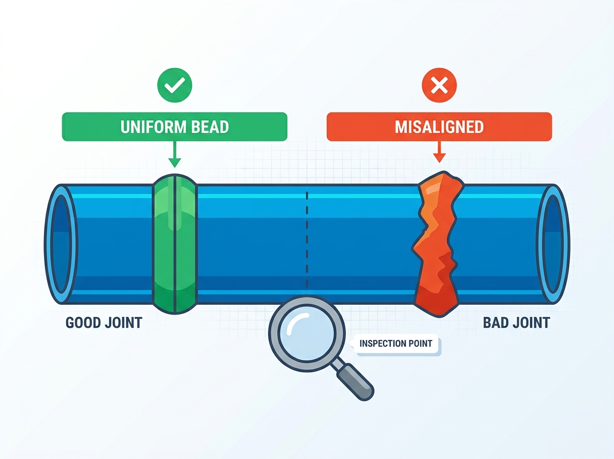
Visual Evidence of Fusion: A compliant joint consistently displays uniform, symmetric "double roll-back" beads with a distinct V-groove valley across the entire circumference, indicating optimal material flow.
Dimensional Tolerances: Proper bead proportions dictate that the width of each lobe should be approximately 2 to 2.5 times its height above the pipe surface, scaling appropriately with the pipe's Standard Dimension Ratio (SDR).
Diagnostic Value of Flaws: Bead abnormalities (e.g., asymmetry, flat profiles, or excessive V-groove depth) directly correlate to specific operator errors in temperature, pressure, alignment, or environmental controls.
Comprehensive QA/QC: While visual inspection is the mandatory first step, high-risk applications require supplementary field tests (like bead bend-back testing), data logging, and Ultrasonic Testing (UT) to guarantee internal joint integrity.
Table of Contents
Toggle
How Butt Fusion Bead Inspection Works
Defining a successful HDPE fusion process requires understanding the physical mechanics of the weld. Proper melting, adequate interfacial pressure, and correct cooling time must align perfectly. The heater plate transfers thermal energy into the pipe ends, mobilizing the polymer chains. Operators then remove the heater and apply fusion pressure. The molten pipe ends press together, forcing the polymer chains to entangle across the interface. This entanglement creates a monolithic structure. The physical manifestation of this entire process is the fusion bead. Evaluating this bead provides direct insight into the internal molecular bond.
Field conditions rarely mimic a controlled laboratory. Operators deal with mud, uneven terrain, and heavy equipment. A successful weld requires the operator to calculate drag pressure accurately before applying fusion pressure. Drag pressure is the force required to overcome the friction of pulling the movable carriage along the machine chassis. If an operator ignores drag pressure, the actual interfacial pressure drops below the required standard. This results in a weak bond. The resulting bead will immediately show signs of insufficient pressure, appearing small or lacking the proper roll-back.
Anatomy of an Optimal HDPE Joint
A correct fusion process produces a very specific visual signature. The most prominent feature is the double roll-back formation. As the pipe ends press together under fusion pressure, the molten material displaces outward and inward. This displacement creates two distinct lobes. These lobes roll back against the outer surface of the pipe. The material must fold over itself smoothly without creating sharp edges.
Between these two lobes lies the V-groove valley. This valley holds significant diagnostic value. The bottom of the V-groove must remain above the outer surface of the parent pipe. If the valley sinks below the pipe surface, the joint lacks sufficient cross-sectional area. This reduces the tensile strength of the connection. The overall profile must appear smooth and rounded. Sharp edges or jagged formations indicate improper material flow or thermal degradation.
Bead size expectations scale directly with the pipe's wall thickness. Heavy-wall pipes with a low Standard Dimension Ratio (SDR) produce massive beads. Thin-wall pipes with a high SDR produce much smaller beads. Inspectors must calibrate their visual expectations based on the specific SDR of the pipeline under construction. A bead size that looks perfect on an SDR 11 pipe indicates a severe over-melt on an SDR 17 pipe. Field crews should always keep a reference chart on hand to verify expected bead dimensions for the specific pipe they are welding.
Industry Standards and Compliance
Field inspections cannot rely on operator intuition. Authoritative frameworks dictate the baseline parameters for acceptable joints. ASTM F2620 serves as the primary standard practice for heat fusion joining of polyethylene pipe and fittings. This standard outlines the exact temperature ranges, heating times, and pressure calculations required for a successful weld.
The Plastics Pipe Institute (PPI) provides further guidance through Technical Report 33 (TR-33). TR-33 details the generic butt fusion procedure and establishes clear visual criteria for bead acceptance. Adhering to these standards ensures municipal and industrial pipelines meet stringent regulatory requirements. Compliance protects contractors from liability and guarantees the longevity of the infrastructure. To maintain compliance, field teams must follow a strict sequence of operations:
Clean the pipe ends and the fusion machine carriage thoroughly.
Face the pipe ends until continuous ribbons of material peel off both sides.
Check alignment and high-low mismatch, adjusting clamps as necessary.
Measure and record the drag pressure for the specific joint.
Apply the heater plate and monitor the initial bead-up phase.
Execute the heat soak phase according to the pipe manufacturer's time requirements.
Remove the heater plate quickly to minimize cooling.
Apply the calculated fusion pressure and hold it for the required cooling cycle.
How to Identify a Good HDPE Butt Fusion Weld
Visual inspection forms the first line of defense in pipeline quality control. Inspectors must evaluate specific physical dimensions to confirm the integrity of the weld. Each visual feature correlates directly to a specific outcome in the fusion process. Mastering these evaluation dimensions allows field teams to identify defects before burying the pipe.
Bead Size and Proportions
Mathematical ratios govern proper bead proportions. The width of each individual lobe should measure approximately 2 to 2.5 times its height above the pipe surface. This specific ratio confirms correct heating and pressure. If the bead grows too tall and narrow, the operator likely applied excessive fusion pressure. This forces the molten material out of the joint interface rapidly. If the bead appears too wide and flat, the heating time likely exceeded the specification. Measuring these proportions requires a simple bead gauge or a trained eye calibrated to the pipe's SDR. Experienced inspectors often carry custom-machined gauges that slip over the bead to instantly verify the width-to-height ratio.
Circumferential Uniformity
Inspectors must examine the entire 360-degree circumference of the weld. The bead must maintain consistent size and shape around the entire pipe. Uniformity verifies consistent material flow. It also confirms the absence of cold spots on the heater plate. A bead that shrinks or swells in specific quadrants indicates uneven heating or improper clamping pressure. Field teams must use mirrors or physical access trenches to inspect the bottom of the pipe. Skipping the bottom quadrant often leaves defects undiscovered. In muddy trench conditions, operators must clear enough space under the pipe to run a mirror along the entire bottom radius.
Alignment and High-Low Tolerances
Pipe alignment directly impacts joint strength. The pipe walls must match up precisely. Industry standards dictate acceptable limits for pipe wall mismatch. The mismatch, often called high-low, must not exceed 10% of the pipe's minimum wall thickness. Excessive high-low creates stress concentrations at the joint interface. This reduces the fatigue life of the pipeline.
Pipe ovality often causes high-low issues. Extruded pipe can become slightly oval during shipping or storage. Operators must use the fusion machine clamps to force the pipe back into a perfect circle. Inspecting pipe-to-fitting joints requires specific attention. Fittings often possess different melt flow indexes or slightly different wall thicknesses than the extruded pipe. This can cause the bead to roll back unevenly. Inspectors must differentiate between an acceptable uneven bead caused by component differences and an unacceptable asymmetrical bead caused by operator error.
Surface Texture
The surface finish of the bead reveals the environmental conditions during the fusion process. An optimal bead displays a smooth, slightly glossy finish. Unacceptable textures include pitting, bubbles, or a sandpaper-like roughness. These textures indicate contamination. Moisture on the pipe ends turns to steam during the heating phase. This steam creates voids and bubbles in the molten polymer. Dust or oil on the heater plate bakes into the bead, creating a rough, contaminated surface. Any deviation from a smooth finish requires immediate investigation. Morning dew represents a common hazard. Operators must wipe the pipe ends with a clean, lint-free cloth immediately before facing and heating.
Internal Bead Inspection
External visual indicators only tell half the story. Inspecting the internal bead ensures the internal flow characteristics match the external formation. Internal beads directly impact pipeline hydraulics. Excessive internal bead size creates flow restriction and turbulence. In gravity sewer applications, large internal beads trap debris and cause blockages. Field teams inspect internal beads using crawler cameras or physical access on large-diameter pipes. The internal bead should mirror the external bead in uniformity and shape, though it often appears slightly smaller due to the mechanics of the fusion machine clamps.
Visual Inspection Criteria Summary
Feature
Acceptable Standard
Unacceptable Condition
Bead Proportions
Width is 2 to 2.5 times the height.
Tall/narrow or excessively wide/flat.
V-Groove Depth
Valley remains above the pipe surface.
Valley sinks below the outer pipe wall.
Circumferential Uniformity
Consistent size and shape 360 degrees.
Varying sizes, shrinking, or swelling.
Alignment (High-Low)
Mismatch under 10% of wall thickness.
Mismatch exceeding 10% of wall thickness.
Surface Texture
Smooth and slightly glossy finish.
Pitting, bubbles, or sandpaper roughness.
Common Butt Fusion Bead Defects and Their Causes
Field execution rarely happens in perfect laboratory conditions. Operators face challenging environments, equipment wear, and tight schedules. These factors introduce implementation risks. Categorizing visual failures and mapping them to their root causes aids in immediate field troubleshooting. Recognizing these abnormalities prevents compromised joints from entering service.
Melt Square or Flat Beads
A square or flat bead profile indicates a severe deviation from the fusion standard. The molten material fails to roll back smoothly against the pipe wall. Instead, it pushes out and forms a blocky, squared-off shape.
Inadequate heating time often causes this defect. The polymer does not reach the necessary molten state to flow properly. Low interfacial pressure during the fusion phase also contributes to flat beads. The machine fails to force the material into the correct roll-back shape. Premature cooling prevents the polymer chains from entangling fully. The primary risk associated with flat beads is cold fusion. Cold fusion creates a weak bond with minimal molecular entanglement. The joint appears solid but suffers from extreme brittleness. A cold fusion joint will fail catastrophically under surge pressure or ground movement.
Asymmetrical or Uneven Beads
Asymmetrical beads feature one lobe significantly larger than the other. The V-groove shifts off-center. This uneven formation points to mechanical or thermal imbalances during the joining process.
Component misalignment serves as the most common cause. If the pipes enter the fusion machine at an angle, the pressure distributes unevenly. Uneven heater plate temperature also creates asymmetry. If one side of the plate runs hotter than the other, one pipe end melts faster. Joining pipes or fittings of different melt indexes or wall thicknesses without proper transition protocols produces similar results. The larger bead forms on the material with the higher melt flow index. Asymmetrical beads create severe stress concentrations. The structural integrity of the joint drops significantly. The pipeline becomes vulnerable to bending stresses and fatigue failure.
V-Groove Too Deep or Too Shallow
The depth of the V-groove valley provides a direct readout of the fusion pressure applied by the operator. Both extremes indicate process failures.
Improper fusion pressure dictates the groove depth. A V-groove that extends below the outer surface of the pipe means the operator applied excessive pressure. The machine pushed too much molten material out of the joint interface. This leaves the connection starved of material. Conversely, a very shallow or non-existent V-groove indicates insufficient pressure. The machine failed to forge the molten ends together with enough force. A deep V-groove reduces the cross-sectional area of the pipe wall. This compromises the tensile strength of the joint. The pipeline may pull apart under thermal contraction or directional drilling loads.
Contamination Indicators
HDPE fusion requires absolute cleanliness. Any foreign material introduced into the melt zone destroys the molecular bond. Visual indicators of contamination include pockmarks, dark streaks, or a rough surface texture on the bead.
Dust, mud, oil, or moisture on the pipe ends cause these defects. Touching the faced pipe ends with bare hands transfers skin oils into the weld zone. A dirty heater plate bakes contaminants directly into the polymer. Contamination creates voids and inclusions within the joint. These microscopic defects act as crack initiation sites. Under cyclic loading, a crack will propagate from the inclusion through the entire pipe wall. This leads to a slow crack growth failure over time. Operators must inspect the heater plate before every single weld. If the Teflon coating shows scratches or burnt plastic residue, the plate requires immediate cleaning or replacement.
Environmental and Weather-Induced Defects
Weather conditions heavily influence the fusion process. HDPE responds rapidly to temperature changes. Environmental factors alter the cooling rate of the bead, leading to visual defects.
High winds strip heat away from the fusion zone rapidly. Rain or snow introduces moisture and causes localized rapid cooling. Extreme ambient cold alters the required soak times and cooling cycles. These conditions cause thermal shock. Thermal shock leads to non-uniform bead formation. The outside of the bead cools and hardens while the inside remains molten. This differential cooling induces severe internal joint stress. Field teams must utilize welding tents and environmental enclosures to mitigate these risks. Failure to control the environment guarantees inconsistent joint quality. To manage weather variables, crews should implement the following steps:
Erect a welding tent over the fusion machine during rain, snow, or high winds.
Cap the open ends of the pipeline to prevent wind from blowing through the pipe and cooling the heater plate.
Store pipe ends off the ground on wooden skids to prevent mud and water contamination.
Adjust heating times based on ambient temperature charts provided by the pipe manufacturer.
Advanced NDT and QA/QC Methods for HDPE Butt Fusion Joints
Visual inspection provides essential baseline data. However, visual checks cannot verify the internal molecular structure of the weld. High-stakes projects require verifiable, data-driven evaluation methods. Transitioning from visual inspection to advanced Non-Destructive Testing (NDT) and physical destructive testing ensures total pipeline integrity. These solution categories eliminate the remaining guesswork from the QA/QC process.
Bead Removal and Bend-Back Testing
A visually perfect bead can still conceal a brittle joint. The bead bend-back test serves as a highly effective field diagnostic tool. This practice involves removing the external or internal bead and subjecting it to physical stress.
Operators use a specialized bead flanging tool to slice the external bead off the pipe seamlessly. This tool removes the bead in one continuous strip without damaging the parent pipe. The operator must maintain a steady hand to avoid gouging the pipe wall. Once removed, the inspector bends the bead back on itself, forcing the root of the weld into tension. The inspector examines the bent bead for slit defects, cracking, or separation. A proper weld allows the bead to bend completely without tearing. If the bead snaps or reveals a slit at the fusion line, the joint suffers from cold fusion or contamination. This physical test reveals hidden brittleness that visual inspection completely misses. It provides immediate, undeniable feedback on the fusion parameters.
Data Logging and Fusion Machine Reports
Modern fusion equipment removes human error from the documentation process. Data logging devices record every parameter of the fusion cycle. These parameters include heater temperature, drag pressure, interfacial pressure, heat soak time, fusion pressure, and cooling time.
The data logger generates a comprehensive joint report for every single weld. Inspectors cross-reference these data logs with their visual inspections. This creates a closed-loop QA process. If a visual inspection reveals a slightly flat bead, the inspector pulls the data log. The log might reveal the operator cut the heating time short by thirty seconds. Data logging provides an immutable record of compliance. It protects the contractor during audits and provides the pipeline owner with a verifiable history of the installation. Many modern machines prevent the operator from proceeding if the parameters fall outside the programmed standard.
Ultrasonic Testing (UT) Solutions for HDPE
When critical infrastructure demands absolute certainty, Ultrasonic Testing (UT) provides the solution. UT technologies adapted specifically for HDPE can detect internal flaws invisible to the naked eye.
Time-of-Flight Diffraction (TOFD) and Phased Array Ultrasonic Testing (PAUT) represent the leading UT methods for plastic pipes. PAUT utilizes multiple ultrasonic elements to sweep a sound beam through the joint interface. The sound waves bounce back from any voids, inclusions, or cold fusion areas. The system generates a detailed cross-sectional image of the weld. TOFD uses two probes to detect the diffraction of sound waves from the tips of internal cracks. These UT methods detect lack of fusion, fine particulate contamination, and voids. Implementing UT on high-pressure gas lines or nuclear cooling water systems guarantees the internal joint integrity meets the highest engineering standards.
Destructive Testing for Procedure Qualification
Before field welding begins, contractors must prove their fusion procedures work. Destructive testing qualifies the procedure and the operators. This testing occurs in a controlled laboratory environment.
High-speed tensile tests pull the fused joint apart at rapid speeds. A successful test results in ductile yielding of the parent pipe before the joint fails. Formal bend tests subject strips of the fused pipe to extreme bending forces to verify ductility. Qualifying the procedure through destructive testing ensures the parameters used in the field will produce reliable joints. It establishes the baseline that all subsequent visual and NDT inspections rely upon.
How to Standardize Butt Fusion Inspection and Quality Control
Implementing a rigorous inspection protocol requires organizational commitment. Field teams must understand the value of the process. Management must provide the necessary tools and training. Standardizing these procedures protects the project from costly rework and catastrophic failures.
Cost of Failure vs. Cost of Compliance
Pipeline decision-makers often weigh the cost of QA/QC against the project budget. Analyzing the return on investment clarifies this trade-off. Investing in certified inspectors, UT equipment, and data-logging fusion machines requires upfront capital. However, the cost of compliance pales in comparison to the cost of failure.
A pipeline rupture results in environmental remediation costs, regulatory fines, and massive liability claims. Repairing a failed joint after burial requires excavation, dewatering, and system downtime. The financial impact of a single catastrophic failure easily exceeds the cost of outfitting an entire fleet with data loggers and funding third-party UT inspections. Compliance acts as an insurance policy against catastrophic financial loss.
Developing Pass/Fail Criteria
Field operations require clear, unambiguous rules. Developing strict pass/fail criteria eliminates subjective bias. Organizations must integrate visual bead inspection checklists into daily field operations.
These checklists must align directly with PPI TR-33 and ASTM standards. The criteria should specify the exact bead width-to-height ratios required for the specific SDR being installed. The checklist must mandate the measurement of high-low misalignment. It must include verification of the V-groove depth. By forcing operators to check off specific dimensional tolerances, the organization ensures consistent evaluation across all crews and projects.
Training and Certification
Equipment and checklists hold no value without competent personnel. Formal training eliminates subjective bias in bead evaluation. Operators and inspectors must understand the physics behind the fusion process.
Training programs must include hands-on bead evaluation. Inspectors need to see examples of cold fusion, over-melt, and contamination. They must practice using bead gauges and flanging tools. Certification programs ensure the inspector possesses the required knowledge to authorize a joint for service. Investing in continuous education keeps field teams updated on the latest NDT technologies and revised industry standards.
Conclusion
Download and distribute a standardized bead inspection checklist to all field operators before the next project phase begins.
Equip your fusion crews with calibrated bead gauges, inspection mirrors, and bead flanging tools to ensure accurate field measurements.
Mandate the use of data-logging fusion machines for all mainline pipe installations to create an immutable record of compliance.
Schedule a certified QA/QC training session for your inspection personnel this quarter to eliminate subjective bias in joint evaluation.
For pipeline projects that depend on reliable HDPE connections, Fusing X brings together the production, research and development, and sales of HDPE fittings, with manufacturing experience dating back to 2005. Its product capabilities cover butt fusion fittings, electrofusion fittings, PE threaded fittings, siphonic drainage fittings, and customized piping solutions, supporting applications across engineering, water treatment, environmental protection, and industrial pipeline systems.
FAQ
Q: What should a proper butt fusion bead look like?
A: A proper bead displays a uniform, symmetric double roll-back formation around the entire pipe circumference. The surface must appear smooth and slightly glossy, free from pitting or bubbles. The V-groove valley between the two lobes must remain above the outer surface of the parent pipe.
Q: How do you measure a butt fusion bead?
A: Inspectors measure the width and height of the bead lobes using a caliper or bead gauge. The width of each lobe should be approximately 2 to 2.5 times its height above the pipe surface. This expected size scales proportionally with the pipe's Standard Dimension Ratio (SDR) and wall thickness.
Q: What causes an asymmetrical fusion bead in HDPE?
A: Asymmetrical beads primarily result from component misalignment in the fusion machine. Uneven heater plate temperatures also cause uneven melting. Additionally, joining pipes or fittings with mismatched wall thicknesses or different melt flow indexes without proper transition procedures will produce an asymmetrical bead.
Q: Can a visually perfect HDPE joint still fail?
A: Yes. A joint can look visually perfect but suffer from cold fusion if the heating time was inadequate or pressure was applied incorrectly. This creates a brittle joint. Bead bend-back testing, data logging, and Ultrasonic Testing (UT) are necessary to detect these hidden internal flaws.
Q: What is the acceptable high-low misalignment for HDPE pipe?
A: Industry standards dictate that the high-low misalignment between two joined pipe ends must not exceed 10% of the pipe's minimum wall thickness. Excessive mismatch creates stress concentrations that severely compromise the long-term structural integrity of the pipeline.
Q: How does moisture or weather affect a butt fusion joint?
A: Moisture turns to steam during heating, causing pitting and bubbles in the bead. High winds or extreme cold cause rapid, uneven cooling. This thermal shock leads to non-uniform bead formation and induces severe internal stress within the joint, requiring the use of environmental enclosures.
Q: What is a bead bend-back test?
A: This field test involves removing the external fusion bead using a specialized flanging tool. The inspector then bends the removed bead back on itself. This physical stress reveals hidden slit defects, contamination, or brittleness that visual inspection cannot detect.

 English
  العربية
  Français
  Русский
  Español
  Português
  Deutsch
  italiano
  日本語
日本語  한국어
한국어  Nederlands
  Tiếng Việt
  ไทย
ไทย  Polski
  Türkçe
  አማርኛ
አማርኛ  ພາສາລາວ
  ភាសាខ្មែរ
  Bahasa Melayu
  ဗမာစာ
ဗမာစာ  தமிழ்
தமிழ்  Filipino
  Bahasa Indonesia
  magyar
  Română
  Čeština
  Монгол
  қазақ
қазақ  Српски
  हिन्दी
  فارسی
فارسی  Kiswahili
  Slovenčina
  Slovenščina
  Norsk
Norsk  Svenska
  українська
  Ελληνικά
  Suomi
Suomi  Հայերեն
  עברית
עברית  Latine
  Dansk
Dansk  اردو
اردو  Shqip
Shqip  বাংলা
বাংলা  Hrvatski
  Afrikaans
  Gaeilge
  Eesti keel
  Māori
Māori