Standard off-the-shelf piping components often fail to accommodate the complex routing, unique spatial constraints, and specialized flow requirements of advanced industrial and municipal systems. When you hit a subterranean utility clash or need a non-standard transition in a tight pump station, standard molded parts simply will not fit. This creates significant engineering and procurement risks. Poorly specified non-standard components threaten system integrity, introduce pressure rating mismatches, and violate stringent regulatory standards. If a fabricated joint fails under operational stress, you face catastrophic leaks and severe environmental compliance violations. To mitigate these risks, you need a rigorous specification framework. Project success depends entirely on precise engineering drawings, strict dimensional tolerances, optimal material selection, and verified manufacturer capabilities. Specifying custom HDPE fittings requires a comprehensive approach to design, material science, and quality assurance to guarantee long-term pipeline performance.
Key Takeaways
Material Integrity: Specifying the correct resin grade (e.g., PE4710 or PE100) and verifying ASTM D3350 cell classifications are foundational for ensuring environmental stress crack resistance (ESCR) and long-term hydrostatic strength.
Dimensional Precision: Custom HDPE fittings require exact matching of the Standard Dimension Ratio (SDR), Pressure Nominal (PN) ratings, and precise Outside Diameter (OD) controls to guarantee seamless butt fusion or electrofusion with existing pipelines.
Pressure De-rating: Fabricated custom fittings (e.g., mitered elbows, wyes, or custom tees) inherently require pressure de-rating calculations compared to molded fittings; system design must account for these structural trade-offs.
Manufacturer Vetting: Reliable procurement demands partnering with fabricators who can provide documented QA/QC processes, hydrostatic testing data, and a proven track record of complex custom fabrications (e.g., minimum linear footage benchmarks).
Table of Contents
Toggle
When Should You Use Custom HDPE Fittings?
Problem Framing and Success Criteria
Defining the threshold where standard fittings become unviable is the first step in pipeline design. Standard off-the-shelf components serve predictable, linear layouts effectively. However, complex topographies quickly render these standard parts useless. Engineers must establish baseline criteria for successful custom integration. Leak-free performance establishes the primary baseline. Uninterrupted flow dynamics prevent cavitation and premature wear inside the pipe. Structural continuity demands exact geometric alignment across the entire pipeline network. When a project requires navigating existing subterranean infrastructure, standard 45-degree or 90-degree angles rarely align with the trench. Forcing standard pipe to bend beyond its allowable bend radius—typically 20 to 25 times the outside diameter—induces unacceptable stress. This stress accelerates material fatigue and eventual failure. Custom geometries eliminate these induced stresses entirely. They provide a tailored solution that respects the physical limits of the polyethylene material while keeping the installation crew moving forward.
Limitations of Off-the-Shelf Polyethylene Fittings
Molded fittings possess strict geometric and manufacturing limitations. Manufacturers produce them in high volumes for common, repetitive applications. Large-diameter applications severely lack off-the-shelf options because injection molding equipment cannot easily accommodate massive diameters like 36-inch or 48-inch pipe. Non-standard angles present another significant limitation in the field. If a trench requires a 62-degree turn to bypass a century-old concrete duct bank, standard fittings force a compromise. Installers might attempt to force the pipe into alignment using heavy equipment. Forced bending creates high-stress points along the pipe wall, which become vulnerable to environmental stress cracking over time. Furthermore, standard tees and wyes often fail to meet specific flow distribution requirements in industrial plants. They create turbulence in high-velocity systems. Custom fabrication addresses these limitations directly by matching the exact required geometry without compromising the structural integrity of the pipeline.
Common Types of Custom HDPE Fittings
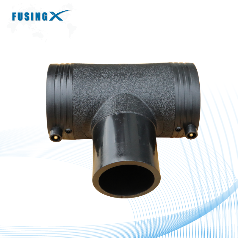
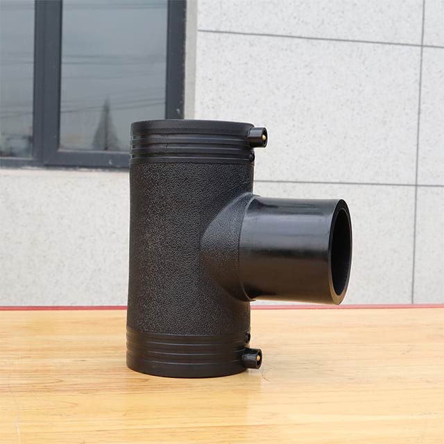
Specific geometries routinely necessitate custom fabrication in the field. We see these requirements daily on complex municipal and industrial job sites.
Long-Radius Sweeps: These sweeps reduce friction losses significantly compared to standard elbows. They maintain fluid velocity and reduce pump energy consumption over long distances.
Complex Wyes: These split flow accurately across multiple distribution lines. Fabricators construct these wyes to exact angular specifications to match the engineered flow dynamics.
Eccentric Reducers: These maintain invert elevations in gravity flow systems. They prevent air pockets from forming at the top of the pipe, which can disrupt flow and cause vapor locks.
Multi-Port Flanged Manifolds: These consolidate numerous connections into a single structural unit. They require precise spacing to accommodate adjacent valves, flow meters, and instrumentation.
Custom Laterals: These allow for branch connections at specific angles to optimize flow dynamics and fit within tight vault spaces.
Applications Requiring Custom Fabrication
Specific scenarios drive the demand for custom orders. Transition joints bridge dissimilar materials safely. Connecting high-density polyethylene to legacy cast iron requires specialized adapters that you cannot buy off a standard supply house shelf. Multi-angle directional changes navigate tight industrial corridors. Chemical processing plants often feature dense networks of existing piping. Threading a new line through this maze demands exact custom angles. Specialized manifold systems optimize pump stations and filtration plants. These systems require compact, high-strength headers to distribute fluid efficiently. Retrofitting legacy infrastructure requires precise adaptation to existing flange patterns. Municipal water authorities frequently encounter non-standard dimensions when repairing century-old systems. Custom fabrication provides the exact missing piece to complete the repair without extensive excavation. Mining operations rely on custom spools to navigate uneven terrain and accommodate heavy, abrasive slurry flows.
How to Choose Materials for Custom HDPE Fittings
Solution Categories and Approaches
High-density polyethylene material grades dictate overall pipeline performance. Aligning resin grades with project environments prevents premature failure. Engineers must evaluate the specific demands of the transported fluid before specifying a material. Operating temperature ranges influence material selection heavily, as polyethylene loses pressure capacity at elevated temperatures. External environmental factors also play a critical role in the longevity of the system. The industry relies on specific resin classifications to standardize performance expectations across different manufacturers. Selecting the correct resin forms the foundation of a durable custom component. A mismatch between material properties and operational demands leads to rapid degradation. Proper selection ensures the fitting matches the lifespan of the adjoining pipeline, which is typically designed for 50 to 100 years of service.
PE100 vs. PE4710 Performance Trade-offs
Two dominant industry standards govern polyethylene pipe materials. PE4710 represents the standard in North America, while PE100 dominates global specifications elsewhere. Both provide exceptional durability and long-term hydrostatic strength, but they have distinct performance profiles.
PE4710 vs. PE100 Material Properties Comparison
Property
PE4710 (North American Standard)
PE100 (International Standard)
Density
High density, allowing for thinner walls at equal pressure ratings.
High density, optimized for high-pressure applications.
Slow Crack Growth Resistance
Exceptional (PENT > 500 hours). Ideal for trenchless installations.
Excellent, but generally lower than PE4710 specific requirements.
Rapid Crack Propagation
High resistance, suitable for gas and high-pressure water.
Superior resistance, specifically engineered for cold weather environments.
Design Stress
1000 psi at 73°F.
8 MPa (approx. 1160 psi) at 68°F.
PE4710 offers superior slow crack growth resistance. This resistance makes it ideal for trenchless installations like directional drilling, where the pipe might drag against rocks. The higher density of PE4710 allows for thinner pipe walls at the same pressure rating. Thinner walls increase the internal diameter and improve flow capacity. PE100 provides excellent resistance to rapid crack propagation. It performs exceptionally well in cold weather environments where brittle fractures are a risk. Engineers must specify the material based on regional availability and specific project requirements. Mixing these materials requires careful evaluation of fusion compatibility, as their melt indexes differ slightly.
Resin Quality and Cell Classification (ASTM D3350)
ASTM D3350 establishes a 6-digit cell classification system for polyethylene materials. This system defines the physical properties of the resin. For example, a common cell class for PE4710 is 445574C. The first digit (4) represents density, which determines the rigidity and tensile strength of the final component. The second digit (4) indicates the melt index. Melt index affects fusion compatibility and extrusion characteristics. The third digit (5) specifies the flexural modulus, dictating the stiffness of the pipe structure. The fourth digit (5) represents tensile strength at yield, establishing the operational pressure limits. The fifth digit (7) measures slow crack growth resistance. High values here indicate excellent long-term durability under stress. The sixth digit (4) indicates the hydrostatic design basis. The final letter (C) designates color and UV stabilizer categories, specifically black with 2% minimum carbon black. Understanding this classification ensures the specified material meets all operational demands.
Environmental and Chemical Resistance Considerations
Material behavior changes under varying environmental conditions. UV exposure degrades standard natural polyethylene rapidly. Outdoor installations demand specific carbon black additives. Carbon black absorbs UV radiation and protects the polymer chains from breaking down in sunlight. Extreme temperature fluctuations require specialized resins and careful engineering. High temperatures reduce the pressure rating of the material. Engineers must apply temperature de-rating factors during the design phase; for instance, water at 100°F requires a 0.78 multiplier on the pressure rating. Aggressive chemical transport necessitates careful material evaluation. Polyethylene resists many acids and bases effectively. However, certain hydrocarbons and solvents can permeate the pipe wall. This permeation weakens the structure over time and can cause swelling. Industrial applications transporting hazardous chemicals may require specialized bimodal resins. These advanced resins offer enhanced chemical resistance and superior structural integrity under harsh conditions.
Custom HDPE Fitting Drawings, SDR, PN, and Dimensions
Evaluation Dimensions and Features-to-Outcomes
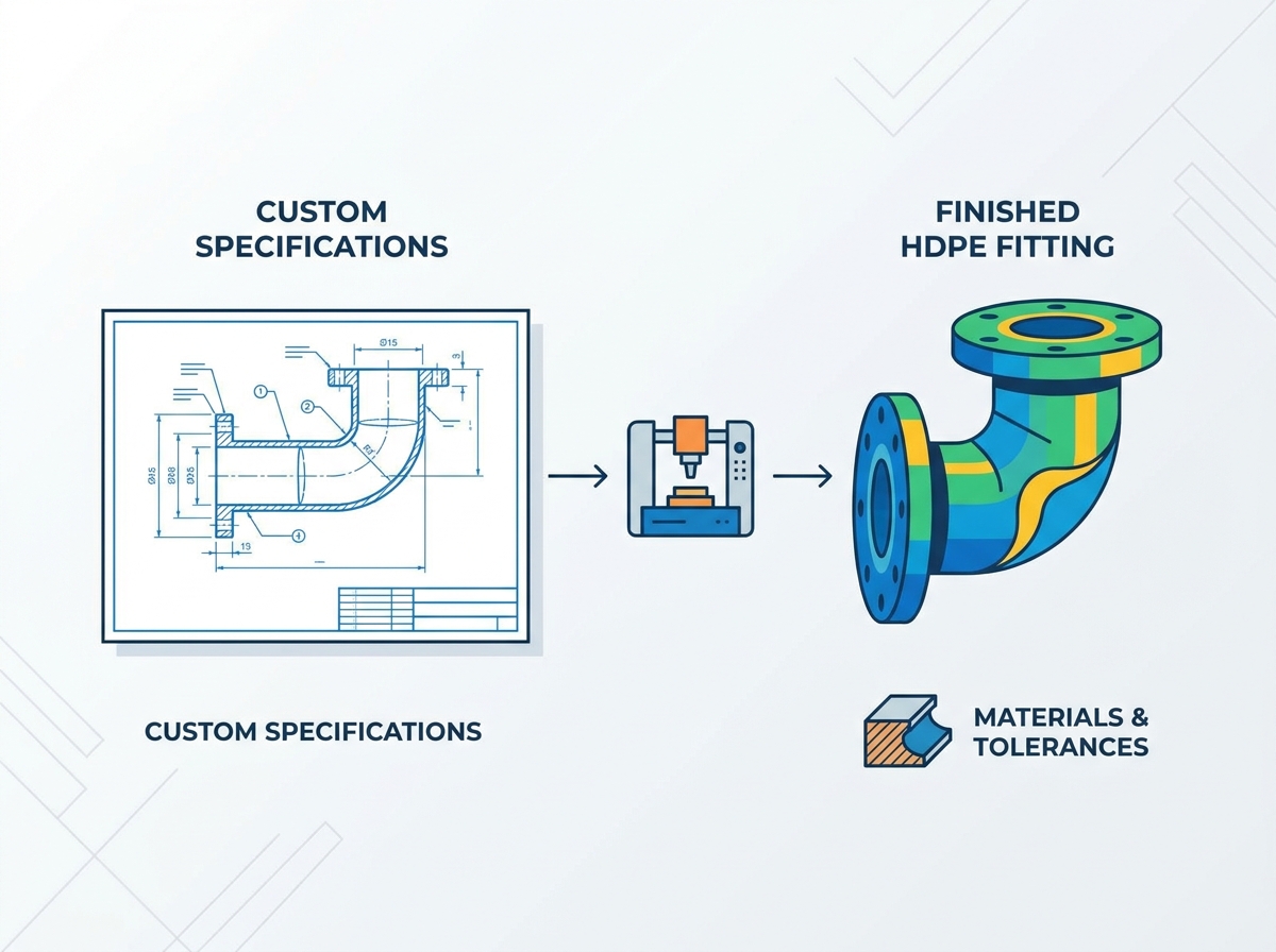
The accuracy of CAD drawings directly impacts installation success. Vague specifications lead to catastrophic field failures and expensive rework. Long-term joint integrity relies on precise geometric alignment. Fabricators build exactly what the drawings specify. If the drawing contains errors, the final component will fail to fit in the trench. Engineers must connect every dimensional feature to a specific installation outcome. A missing tangent length prevents the fusion machine from clamping the pipe. An incorrect angle forces the entire pipeline out of alignment, requiring the crew to dig a wider trench or force the pipe. Detailed engineering drawings eliminate ambiguity. They provide a clear roadmap for the fabrication team. High-quality drawings include detailed cross-sections, exact laying lengths, and precise tolerance callouts. This level of detail guarantees the custom component integrates seamlessly into the broader system.
SDR, Wall Thickness, and PN Matching
Matching the Standard Dimension Ratio prevents internal flow disruption. SDR represents the ratio of the outside diameter to the wall thickness. Pressure Nominal ratings must align across all connected components. Uniform fusion pressure requires identical wall thicknesses at the joint. If a fabricator joins a thin-walled fitting (SDR 17) to a thick-walled pipe (SDR 9), the fusion process fails. The heating plate melts the thin wall faster than the thick wall. This mismatch creates a weak, unreliable joint that will fail under pressure. Furthermore, mismatched internal diameters create a lip inside the pipe. This lip causes turbulence, accelerates wear, and increases friction losses. Engineers must clearly specify the required SDR and PN rating on all custom drawings. This ensures global metric compatibility and maintains the structural integrity of the pipeline.
Outside Diameter (OD) vs. Inside Diameter (ID) Control
Manufacturing focuses heavily on Outside Diameter control. OD consistency guarantees compatibility with standard fusion equipment. Clamping jaws on a McElroy or Ritmo machine rely on a predictable outside diameter to secure the pipe during the fusion process. Custom wall thicknesses alter the Inside Diameter. As the pressure rating increases, the wall thickness grows inward. This inward growth reduces the ID. ID changes directly impact flow rates and friction losses. Engineers must calculate these losses during the design phase. A heavily reinforced custom fitting might restrict flow more than anticipated. Understanding the relationship between OD control and ID variation allows designers to compensate for potential flow restrictions by adjusting pump sizing or selecting a larger nominal pipe size for the manifold section.
Critical Drawing Annotations for Custom Fabrications
Submitted drawings require mandatory elements to ensure accurate fabrication. Missing any of these details will halt production or result in an unusable part.
Exact Laying Lengths: Installers need to know exactly how much space the fitting will occupy to cut the existing pipe accurately.
Tangent Lengths: These represent the straight sections at the ends of the fitting. They ensure fusion equipment has enough clearance to clamp securely. Without sufficient tangent length, butt fusion becomes impossible.
Angular Degrees: Drawings must specify the exact angle required to navigate the site topography.
Tolerance Callouts: A drawing might specify a 22.5-degree elbow. The tolerance callout dictates whether 23 degrees is acceptable.
Flange Specifications: Flange bolt hole patterns must align precisely with existing infrastructure. Drawings must specify the exact flange standard required (e.g., AWWA C207 Class D).
How Custom HDPE Fittings Are Manufactured and Toleranced
Overall Value Influencing Factors
Manufacturing methods impact cost and lead time significantly. Structural strength varies drastically by fabrication approach. Engineers must balance these conceptual trade-offs during specification. An injection-molded part offers high strength but limited geometric options and size availability. A fabricated part offers infinite geometric flexibility but requires pressure de-rating and specialized labor. The choice depends entirely on the project constraints. Tight budgets might force a redesign to utilize standard molded parts. Critical flow requirements or immovable subterranean obstacles might justify the expense of complex fabrication. Understanding these value influencing factors helps procurement teams make informed decisions. It ensures the final component delivers the required performance without unnecessary expenditure.
Molded vs. Fabricated Fittings Structural Integrity
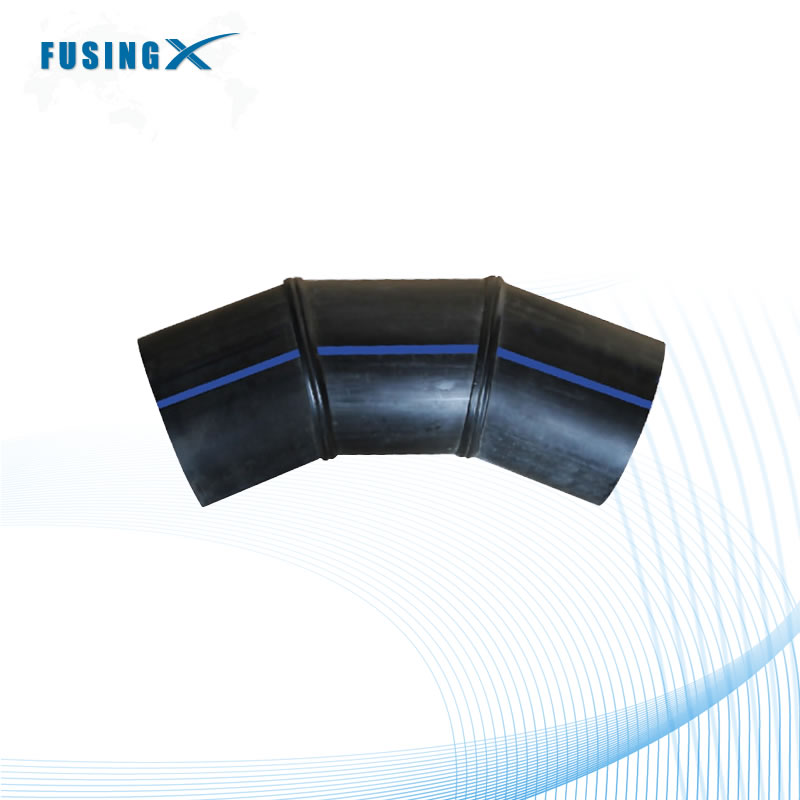
Injection-molded components feature a homogeneous structure. The manufacturing process injects molten resin into a steel mold under high pressure. This creates a single, continuous piece of material. Molded parts handle stress evenly across their geometry. Fabricated components utilize mitered cuts and thermal fusion. Fabricators cut straight pipe sections at specific angles using large band saws. They then face the ends, heat them, and fuse these sections together to create the desired shape. Mitered joints introduce structural trade-offs. The fusion seam represents a potential stress concentration point. While a properly executed fusion joint is as strong as the parent pipe, the geometry of a mitered elbow concentrates internal pressure at the sharp inner angles of the seams. This concentration necessitates careful engineering analysis and mandatory pressure de-rating.
Resin and Batch Compatibility for Butt Fusion
Municipal codes often require identical resin batches for critical infrastructure. Using pipe from the same manufacturer guarantees homogeneous butt fusion joints. Different manufacturers use slightly different resin formulations. Even if both resins meet the same ASTM standard, their melt flow indexes might vary. Fusing pipes with different melt flow indexes creates a substandard joint. The materials melt and cool at different rates. This discrepancy induces internal stresses within the fusion zone, leading to premature failure. To mitigate this risk, specifications often demand that custom fabrications utilize pipe sourced from the same lot as the main pipeline. This strict compatibility requirement ensures maximum joint strength and long-term reliability in the field.
Fusion Compatibility and Preparation
Preparation tolerances ensure compatibility with field equipment. Standard field fusion equipment requires precise fitting ends. The ends must be perfectly square and clean. Any deviation prevents the heating plate from making uniform contact, resulting in cold spots and weak fusions. Electrofusion requires specific scraping and cleaning protocols. The outside diameter of the fitting must match the inside diameter of the electrofusion coupler precisely. If the fitting is slightly out of round, the coupler will not slide over it. Fabricators must ensure the final product meets these strict preparation tolerances. They often use specialized facing tools to square the ends before shipping. This attention to detail prevents costly delays during field installation.
Acceptable Tolerance Ranges for Angles and Laying Lengths
Industry standards dictate acceptable deviations for custom geometries. Custom angles typically allow a ±1 degree deviation. A 45-degree elbow might arrive measuring 44 or 46 degrees. In long pipe runs, a one-degree deviation causes significant misalignment. Installers must compensate for this deviation in the trench by utilizing the natural flexibility of the polyethylene pipe. Laying lengths also have defined tolerances, often ±1 inch depending on the total size of the fitting. Tighter tolerances exponentially increase fabrication costs. Demanding a ±0.1 degree tolerance requires specialized machining and extensive quality control. Engineers must specify tolerances that balance installation feasibility with fabrication costs. Over-specifying tolerances wastes project funds without providing tangible benefits.
Custom HDPE Fitting Standards, Testing, and Quality Control
Evaluation Dimensions for Compliance
Regulatory frameworks validate the safety of custom components. Testing ensures durability under operational stress. Compliance is not optional; it is a legal requirement. Municipalities and industrial operators demand proof of compliance before installation. This proof protects them from liability in the event of a failure. The evaluation dimensions focus on material properties, dimensional accuracy, and joint integrity. Independent laboratories often conduct these evaluations to ensure objectivity. A rigorous compliance framework guarantees the custom fitting will perform as designed for its intended lifespan, handling surge pressures and environmental loads without yielding.
Navigating ASTM and AWWA Standards
Specific requirements govern material dimensions and test methods. Understanding these standards is critical for accurate specification.
Common ASTM and AWWA Standards for Polyethylene Systems
Standard Designation
Scope and Application
Key Requirements Addressed
ASTM D2513
Natural gas distribution systems.
Material dimensions, rapid crack propagation testing, strict QA/QC.
Dimensional tolerances, material compatibility, burst pressure testing.
ASTM F714
Large diameter polyethylene pipe.
Outside diameter controls, wall thickness variations, heavy industrial use.
AWWA C906
Water and wastewater distribution.
Surge pressure allowances, municipal compliance, hydrostatic design basis.
ASTM D2513 governs gas distribution strictly. It demands rigorous testing to prevent catastrophic leaks. ASTM F2206 covers fabricated fittings specifically. It dictates how fabricators must construct and test mitered joints. ASTM D3261 details butt heat fusion requirements. AWWA C906 dictates municipal water applications. Engineers must cite the correct standards on their drawings. This ensures the fabricator follows the appropriate testing and construction protocols.
Pressure Rating De-rating Factors for Fabricated Geometries
Fabricated geometries require mandatory pressure de-rating. Engineering math dictates the specific multipliers. A custom mitered elbow cannot carry the straight pipe pressure rating. The mitered cuts alter the stress distribution within the pipe wall. Internal pressure concentrates at the sharp angles of the fusion seam. To compensate, engineers apply a design multiplier based on the geometry. A 3-segment 90-degree mitered elbow might require a 0.75 multiplier. If the straight pipe handles 160 PSI (SDR 11), the fabricated elbow only handles 120 PSI safely. System design must account for these structural trade-offs. If the system requires 160 PSI throughout, the fabricator must build the elbow from thicker-walled pipe (e.g., SDR 9 or SDR 7) to achieve the required final rating after applying the de-rating multiplier.
Non-Destructive Testing (NDT) and Hydrostatic Testing
QA/QC protocols are mandatory for custom fabrications. Visual inspection of the fusion bead alone cannot guarantee joint integrity. Ultrasonic testing verifies the internal structure of fusion joints. Phased array ultrasonic testing (PAUT) detects microscopic voids, inclusions, and cold fusions hidden deep within the wall. Batch hydrostatic pressure testing confirms structural integrity. Fabricators cap the ends of the fitting and fill it with water. They pressurize the component to a specific multiple of its operating pressure, often 1.5 times the rated capacity. The fitting must hold this pressure for a designated time without leaking or expanding excessively. Documented results from these tests provide the necessary evidence of compliance and safety.
How to Choose a Custom HDPE Fittings Manufacturer
Implementation Risks and Mitigation
Vendor selection mitigates severe implementation risks. Receiving out-of-spec fittings causes massive project delays. Crews sit idle while waiting for replacement parts, burning through the project budget. Structurally unsound components threaten operational safety. A failed custom manifold can flood a pump station or release hazardous chemicals into the environment. Procurement teams must look beyond the lowest bid. They must evaluate the technical competence of the fabrication facility. A rigorous vetting process separates reliable partners from high-risk vendors. Mitigation strategies include demanding detailed QA/QC manuals, reviewing past project submittals, and conducting facility audits before awarding the contract.
Assessing Fabrication Capacity and Track Record
Vetting requires concrete evidence of past performance. Look for a minimum history of 10,000 linear feet of piping produced. This benchmark proves the facility handles high-volume, complex work regularly. ISO 9001 certifications demonstrate a commitment to standardized quality control. Case studies prove complex geometry capabilities. Ask the vendor for examples of multi-port manifolds or large-diameter eccentric reducers they have successfully delivered. Review their equipment list. Do they possess the large-scale fusion machines required for your specific SDR and OD? A proven track record provides confidence that the manufacturer can execute the required engineering drawings accurately.
Supply Chain Constraints and Lead Time Drivers
Resin availability impacts project timelines directly. Specialized bimodal resins often require long lead times from the chemical plant. Custom tooling extends fabrication schedules. If a project requires a unique flange adapter, the fabricator might need to machine custom clamping jaws. QA testing schedules require significant buffering. Hydrostatic testing takes time to set up, execute, and document. Procurement teams must discuss these drivers with the manufacturer early in the process. Strategies to buffer schedules include ordering critical custom components months before the standard pipe arrives on site. Transparent communication regarding lead times prevents unexpected delays.
Cost Drivers in Custom Fabrication
Pricing models for custom fabrications involve multiple variables. Engineering time represents a significant upfront cost. Draftsmen must convert conceptual sketches into precise CAD models. Mitered cuts generate substantial material waste. Fabricating a complex wye might require cutting up and discarding large sections of expensive pipe. Specialized labor increases overhead. Certified fusion technicians command higher wages than standard assembly workers. Testing adds to the final cost. Ultrasonic inspection requires expensive equipment and highly trained operators. Understanding these cost drivers helps procurement teams evaluate quotes accurately. It allows them to distinguish between a genuinely competitive bid and one that cuts corners on quality assurance.
Conclusion
Audit current system requirements to identify all non-standard routing locations and spatial constraints.
Finalize CAD drawings with explicit SDR, PN, exact laying lengths, and tangent length callouts.
Submit detailed specifications to a vetted fabrication partner for a comprehensive technical review.
Demand complete hydrostatic testing and phased array ultrasonic testing documentation before accepting delivery.
Established in 2005, Fusing X integrates the R&D, manufacturing, and sales of HDPE pipe fittings, with capabilities covering butt fusion fittings, electrofusion fittings, threaded fittings, drainage systems, and customized fittings. With a 20,000 m² production facility, around 300 employees, and products supplied to more than 20 countries, the company provides manufacturing and customization support for demanding polyethylene piping projects.
FAQ
Q: What is the difference in pressure rating between molded and fabricated custom HDPE fittings?
A: Molded fittings generally maintain the same pressure rating as the corresponding pipe. Fabricated fittings require de-rating multipliers due to the stress concentrations introduced by mitered cuts and fusion seams. A heavily mitered elbow will have a lower operational pressure limit than a straight pipe of identical material. Engineers must apply these multipliers to ensure safety.
Q: How do I determine the correct SDR and PN rating for a custom HDPE fitting?
A: Determine the maximum operating pressure of your system, including potential surge pressures. Match the PN rating to this maximum requirement. Next, ensure the fitting's SDR matches the adjoining pipeline's wall thickness. This matching prevents internal flow disruption and guarantees uniform heating and pressure during the butt fusion process.
Q: What are the standard tolerances for custom fabricated HDPE angles?
A: Industry benchmarks typically allow for an angular deviation of ±1 degree on custom fabricated angles. Laying length tolerances generally fall within ±1 inch, depending on the overall size of the component. Demanding tighter tolerances is possible but requires specialized machining and exponentially increases the final fabrication costs.
Q: Can custom HDPE fittings be joined to standard PVC or steel pipes?
A: Yes, they can be joined using specialized transition methods. Custom mechanical joint (MJ) adapters allow for secure connections to ductile iron or PVC. Flange connections, utilizing HDPE flange adapters and metal backup rings, provide a robust method for bolting the polyethylene system directly to standard steel flanged infrastructure.
Q: What information is required to get an accurate quote for a custom HDPE fitting?
A: An accurate quote requires precise details. You must provide the exact Outside Diameter (OD), the required Standard Dimension Ratio (SDR), the specific material grade (e.g., PE4710), maximum operating pressure, fluid type, and operating temperature. Most importantly, you must supply detailed dimensional CAD drawings showing all angles and tangent lengths.
Q: Are custom fabricated HDPE fittings compliant with ASTM D2513?
A: They can be, provided they meet strict criteria. To comply with ASTM D2513 for gas distribution, the custom fitting must utilize approved resin grades, adhere to specific dimensional tolerances, and pass rigorous destructive and non-destructive testing protocols. The fabricator must maintain comprehensive QA/QC documentation to prove compliance.

 English
  العربية
  Français
  Русский
  Español
  Português
  Deutsch
  italiano
  日本語
日本語  한국어
한국어  Nederlands
  Tiếng Việt
  ไทย
ไทย  Polski
  Türkçe
  አማርኛ
አማርኛ  ພາສາລາວ
  ភាសាខ្មែរ
  Bahasa Melayu
  ဗမာစာ
ဗမာစာ  தமிழ்
தமிழ்  Filipino
  Bahasa Indonesia
  magyar
  Română
  Čeština
  Монгол
  қазақ
қазақ  Српски
  हिन्दी
  فارسی
فارسی  Kiswahili
  Slovenčina
  Slovenščina
  Norsk
Norsk  Svenska
  українська
  Ελληνικά
  Suomi
Suomi  Հայերեն
  עברית
עברית  Latine
  Dansk
Dansk  اردو
اردو  Shqip
Shqip  বাংলা
বাংলা  Hrvatski
  Afrikaans
  Gaeilge
  Eesti keel
  Māori
Māori